What is return loss?
Return loss, referred to as RL, uses the returned light wave to define the loss of the emitted light wave;
Return loss=10lg (incident light/reflected light)
(Unit:dB)
Why do optical devices need to measure return loss?
Before answering this question, first explain the optical path of the optical device, and then everyone can understand;
The following is the optical power test of the TOSA transmitting optical device, the current is applied to both ends of Pin and the optical power of the fiber end is emitted;
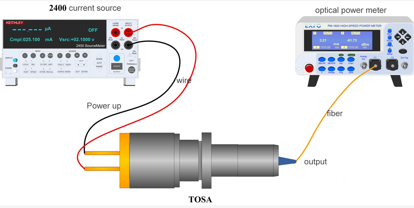
Refine the structure of TOSA:
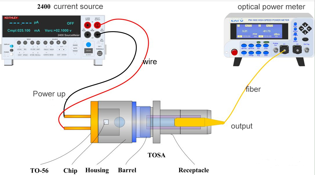
What is the housing/barrel/receptacle?
Everyone understands that "all are accessories, and the purpose is to fix Chip and fiber coaxial";
Draw the laser light path (red):
Chip emits laser light, converges through lens, couples into optical fiber to measure power value;
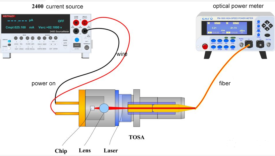
To further dissect TOSA:
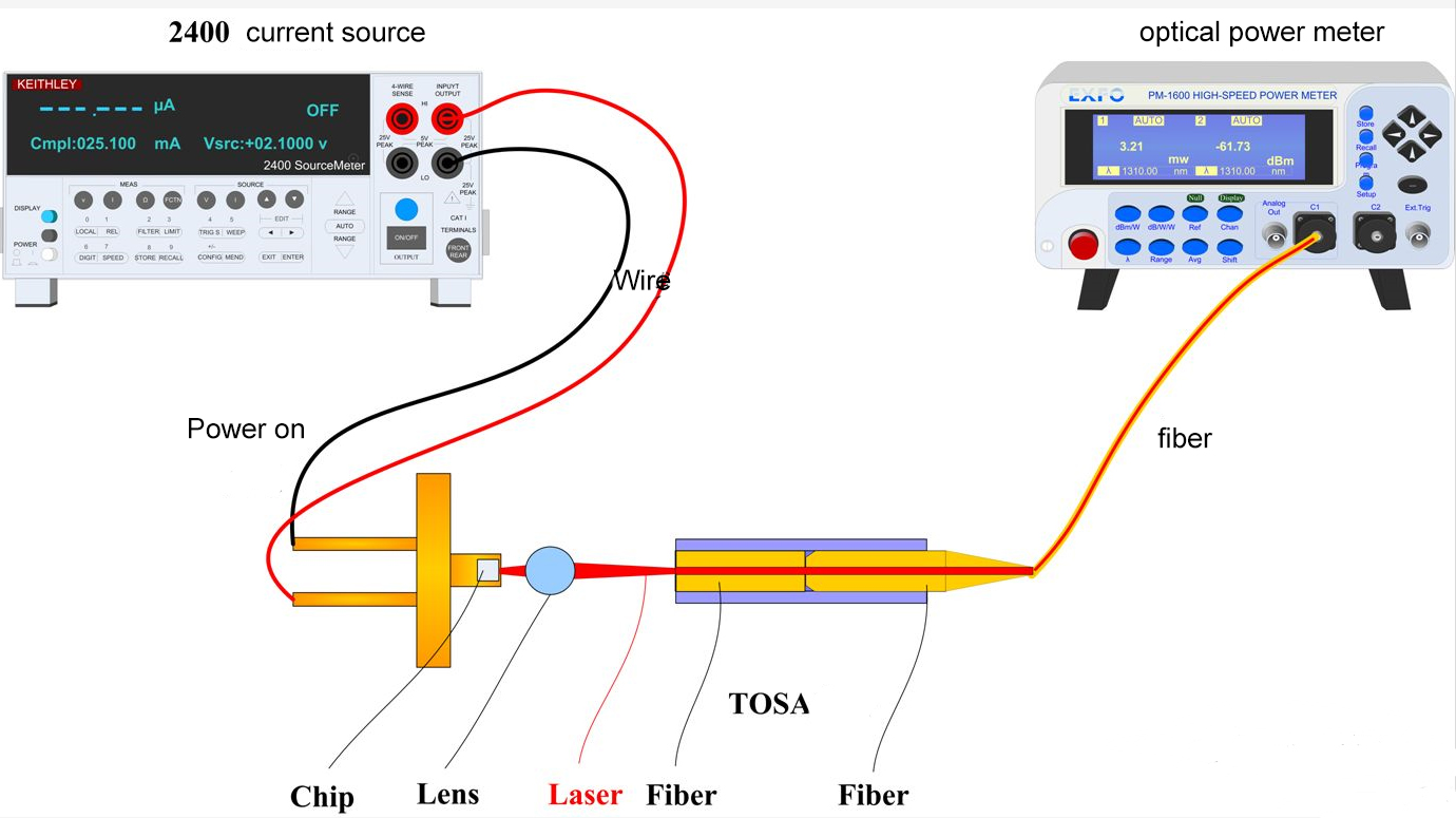
The laser is emitted from the Chip, and each interface (such as lens surface, fiber end surface) will produce different degrees of reflected light;
The accumulation of reflected light to a certain extent will affect the performance of Chip and endanger the entire optical communication system;
We always expect the lowest reflection value, so we need to monitor the reflected light;
How to measure it?
Chip is sealed inside the TO-56 tube body, it is impossible to directly measure the reflected light;
Then take the indirect measurement method: the light path is in the opposite direction, and a beam of light enters from the right fiber end, and the reflected light is measured. 10*Log (incident light/reflected light) is the return loss;
Due to the reversibility of light, qualitatively evaluate the internal reflection of optical devices;
How to measure return loss specifically?
We choose to use 1:2 splitter to test:

Build a return loss test structure:
Below, the optical power meter is switched to the dBm position;
1. The light source emits light, the optical power meter receives it, and the PL is measured;
2. The light source emits light, enters from the A road and exits from the B road, and PB is measured;
3.The light source emits light, enters from the B road and exits from the C road, and PB-C is measured;
4. The light source emits light, enters from the A road, returns via the B road, and exits from the C road, and Pc is measured;
Return loss RL=PB-Pc-PB-C+PL;
The origin of this formula is nothing more than to compensate for interference light such as stray light entering the fiber from all directions, and only obtain the value of the light reflected by the TOSA;
Collect test data, analyze, eliminate gross errors, and finally get the return loss measurement value;
After doing so much work, the return loss is finally measured. It seems to be great, right?
I regret to tell you: this measurement method is of little significance. The test process is complicated. If you are not careful, the fiber end face of a certain link is dirty, and the test result will have an error of more than 10dB, which will lead to the use of all previous efforts;
The following is a detailed diagram of the last test step of the return loss test:
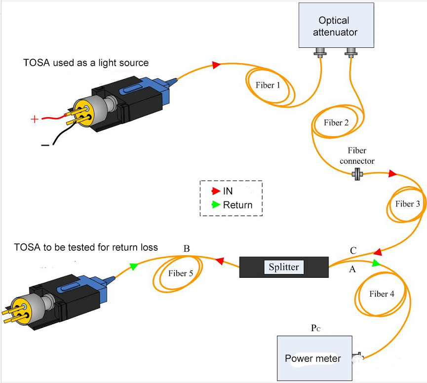
Sources of error introduced during testing:
1. The fiber end face is dirty;
2. Each time the fiber is connected, the concentricity is different and the tilt angle is different;
3. The connector is not tightened;
4. Influence of light source stability;
5. Linear error, such as switching the measurement gear from 0.1dB to 0.01dB during the test;
6. The movement and mechanical stretching of the optical fiber change the polarization state of the light in the optical fiber;
Why do we need to consider so many small error sources when measuring return loss?
Because the accuracy of return loss measurement is too high;
For example, RL=20dB,
What concept?
20dB=10*Log (incident light/reflected light);
Then 10*Log (reflected light/incident light)=-20dB;
It is obtained that reflected light/incident light = 1%;
If TOSA emits 1mW, reflected light=1mW*1%=0.01mW;
It can be seen that the magnitude of the reflected light is very small, so it is very sensitive to error sources;
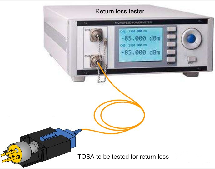
Therefore, if you want to measure the return loss, you should choose a professional return loss tester:
It can be measured by connecting a fiber. The principle is similar to the above steps.
The difference is that the error source and other factors are integrated into the instrument’s internal filtering and compensation.
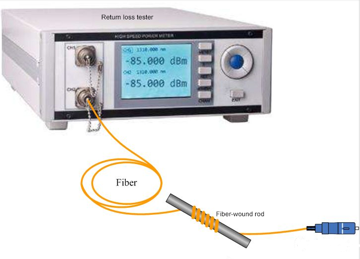
Return loss instrument in kind:
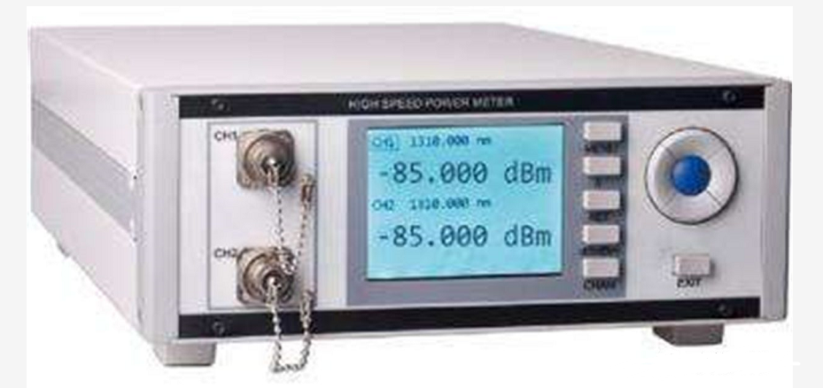
Schematic diagram of return loss tester:
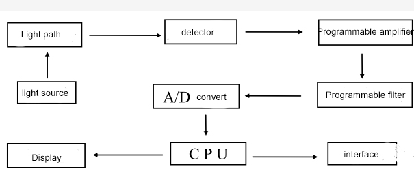
The test only requires two steps:
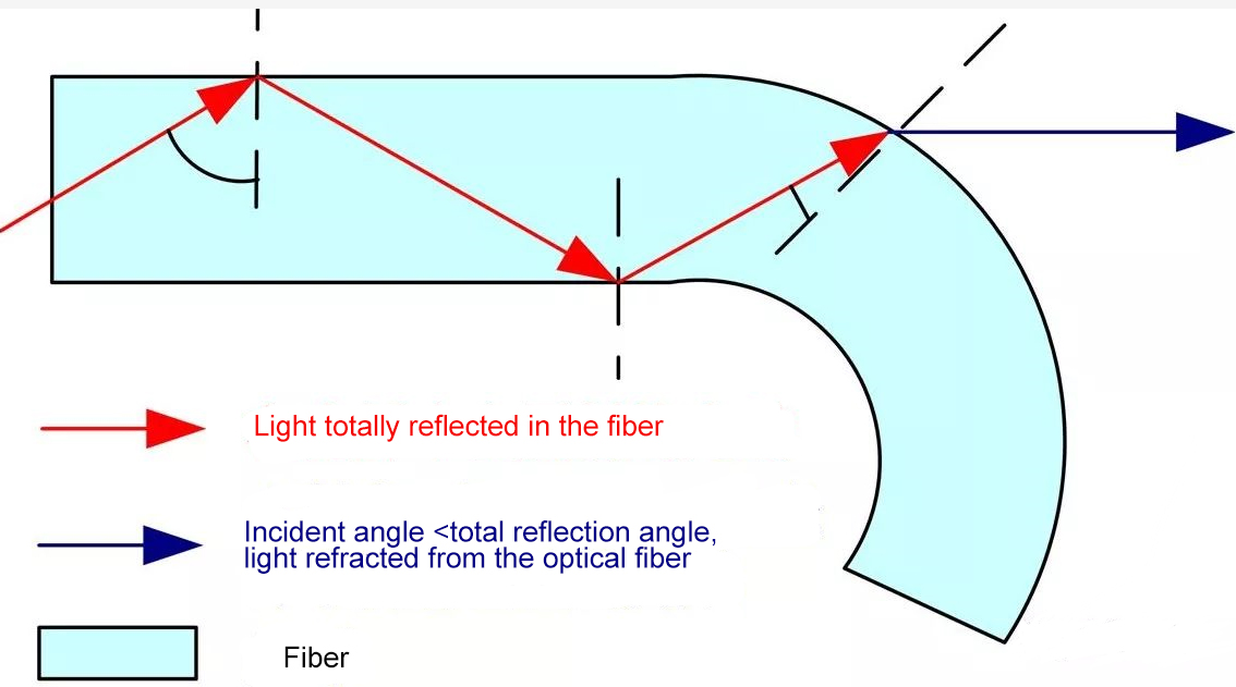
1. Calibrate, use 3D standard optical fiber that conforms to the protocol, wind 5 turns (to filter the light from the optical fiber) on a winding rod with a diameter of 3~5mm to zero, then loosen the wound optical fiber, and return loss at this time If the return loss value displayed by the meter is 14.9dB, the calibration is OK (calibration to air method);
The principle of fiber winding and filtering: using the bending loss characteristics of the fiber to make the incident angle <the total reflection angle, the light is refracted from the fiber;
2. Connect the optical device to be measured to the calibrated return loss meter, and the return loss value can be measured;
